Audio Pre-amp
This audio pre-amp is a part of the Custom Bass Guitar project. This pre-amp is used to provide more control over the sound of the bass. Specifications for this project were derived from available pre-amps, specifically the Aguilar OBP-3TKPP.
Target Specifications
- 3-Band Equalizer
- 40 Hz: $\pm$ 16 dB
- 450 Hz: $\pm$ 13 dB
- 6.5 kHz: $\pm$ 13 dB
- Input Impedance 1 M$\Omega$
- Output Impedance 100 $\Omega$
- 9 or 18 Volt PS
Circuit Design
External links will open the image in a new tab to show the details of the circuit/image.
External Link: Full Circuit Schematic
Power Supply
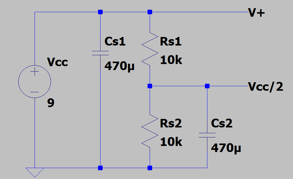
Below is the power supply used for the circuit. Notice the voltage divider, which is used to provide room for the signal to swing from $V_{cc}/2$ instead of ground because we do not actually have a negative voltage for negative rail.
Input Stage
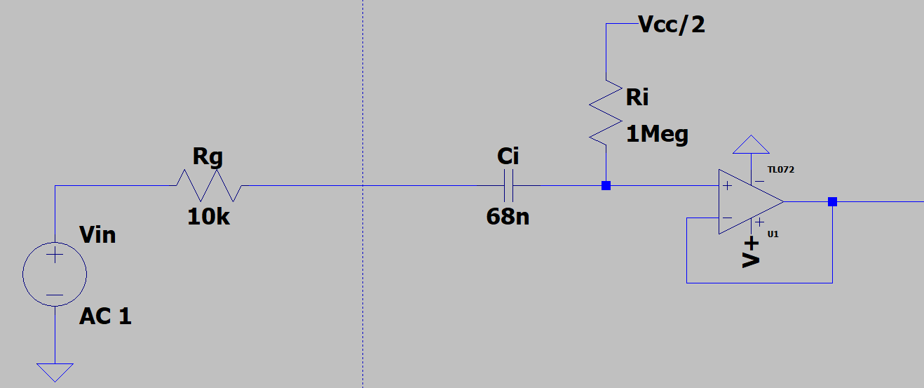
The input stage of this circuit will set both the input resistance and -3dB $f_{low}$ point, which should be below 10 Hz.
Gain Stages
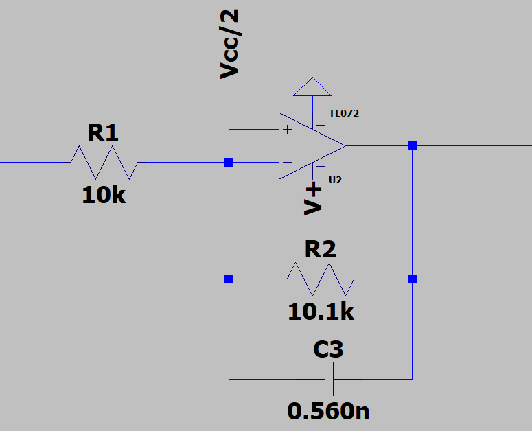
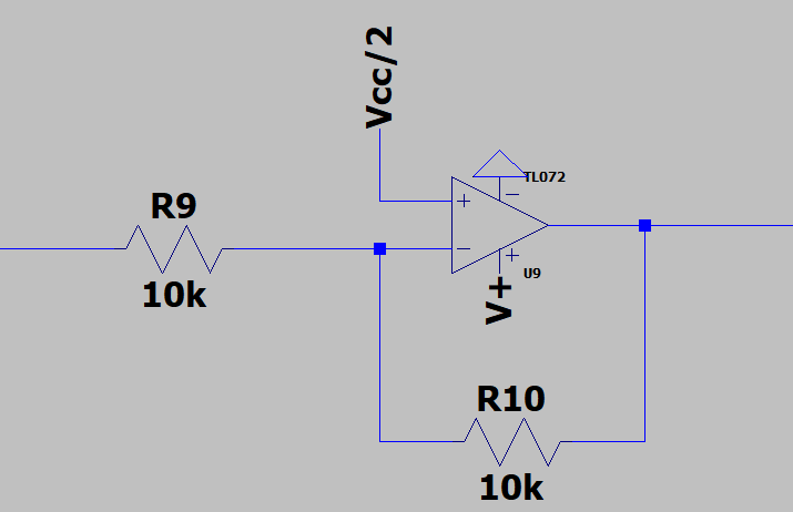
These stages bridge the input and output stages to the Boost/Cut circuit, which are used to tune the baseline gain. The coupling capacitors cause some drop in the gain, which is counter acted by these stages. Note in the gain stage directly after the input stage a capacitor provides a feedback path, which is used to reduce the range for this circuit. This was used to hopefully save some DC power. The capacitor sets the $-3dB$ high frequency, ~27 kHz.
Input Gain Stage
Output Gain Stage
Kenneth James Boost/Cut Circuit
External Link: Boost/Cut Circuit
Active Filters Stage
The active filter stage consists of a 3 band pass filters. The targeted frequency were 40, 450, and 6,500 Hz.
The link below opens the actual circuit in a new tab and has the exact values listed.
External Link: Active BP Circuit
Output Stage
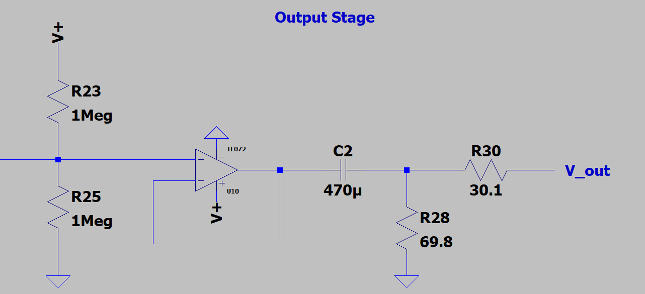
Looking at the output, we can see that a large capacitor is found in series with the signal path. This is the main result of only having a positive voltage and ground for the amplified signal to swing between. A zero DC offset is a must for any low impedance load that might be connected to the output. Typically the load connected would be around 10 times the output resistance of the circuit, but we must account for accidents and miss-use. This means we need to have a capacitor at the output, but the size of the capacitor comes from the desired output resistance and where the -3 dB corner is placed. Our output resistance is targeted at 100 $\Omega$, so we need a large capacitance to have a -3 dB corner lower than 40 Hz.
Simulation Results
Bass Response
Mid Response
Treb Response
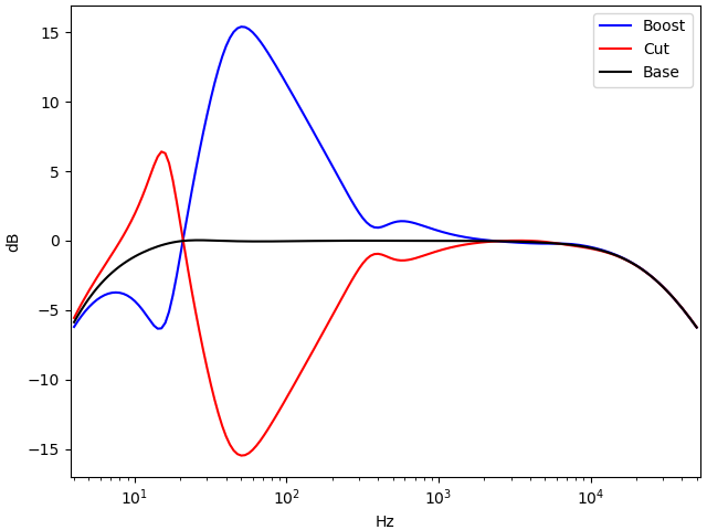
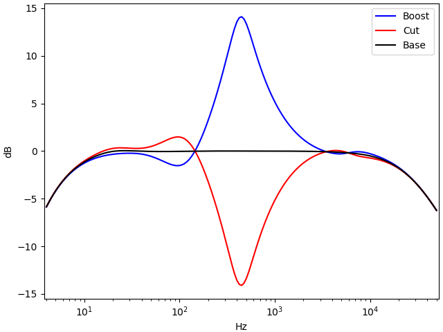
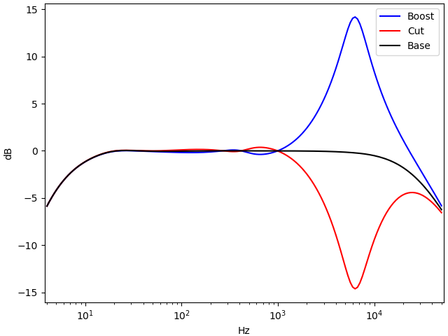
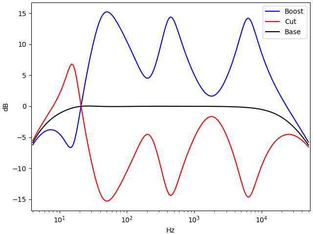
From the different frequency responses shown above, the various BP filters work well and have little interference with frequencies outside of one order of magnitude, which is important for isolated control. One somewhat alarming issue would be the Bass Response showing extreme changes to the left of the targeted peak. However, this is perfectly fine with regards to what frequencies the instrument will produce because the lowest note for the bass is 41 Hz.
Level Response
Full Boost/Cut Response
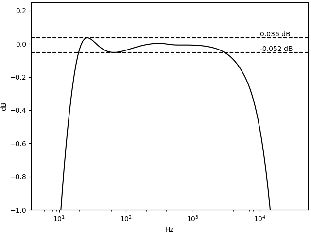
Looking at the level response, where no boost or cut was applied, we can see a slight overshoot meaning an under-damped system. However, the specific value of $\zeta$, the damping coefficient, is very close to one. Ideas to fix this might include adding a snub network or filter, but considering the size of the overshoot it is not an important detail. It will be more time efficient to wait until a prototype is made and determine how close this simulation is to the actual circuit.
Future Work
Currently no prototype has been made and tested. This is only the design, and hopefully I can order a PCB after I maKe a perf board prototype and verify the circuit results to the simulations. For the prototype I am only missing the two 25k potentiometers and a handful of the capacitors, which I plan to purchase from the UTK parts store.
